Compressed air school
Welcome to the Compressed Air School, where you can learn about compressed air, compressors and much more!
Download the Compressed Air School as PDF
Download the document "Simple faults" for reciprocating compressors
AIR VOLUME
I'm glad you want to go to compressed air school!
A compressor must produce a certain flow (capacity); amount of air, or volume, per unit of time. All capacities are measured in m³/min, l/min or l/s and indicate the pressure at which they are measured.
This value is called Free Air Volume (FAL).
(Example; K-MID10-270F-ES delivers 1050 l/min FAD at 9 bar.)
The measurement standard you should normally use is ISO 1217.
AIR PRESSURE
A compressor must compress the compressed air to a certain pressure, usually 8 - 10 bar. (Higher pressures can occur, for example, in tyre inflation and blasting, etc.)
The pressure to be applied at each point of use should be set with a regulator and is determined by the application. Manufacturers of air motors, paint sprayers, pneumatics or similar usually specify at what pressure their product should be used (i.e. Read manuals!)
Some examples of what prints you might need for common uses:
- To blow clean, about 6-8 bar
- To drive an air motor, e.g. grinder, nutrunner etc., approx. 6-8 bar
- Operate pneumatics, such as cylinders and valves etc., normally 6-7 bar
AIR QUALITY
As compressed air is commonly used in everything from workshops to laboratory environments, there may be different requirements for the quality of the compressed air, some common criteria to assess are:
- Water/oil content
- Particle content
- Sterility
- Odour/taste
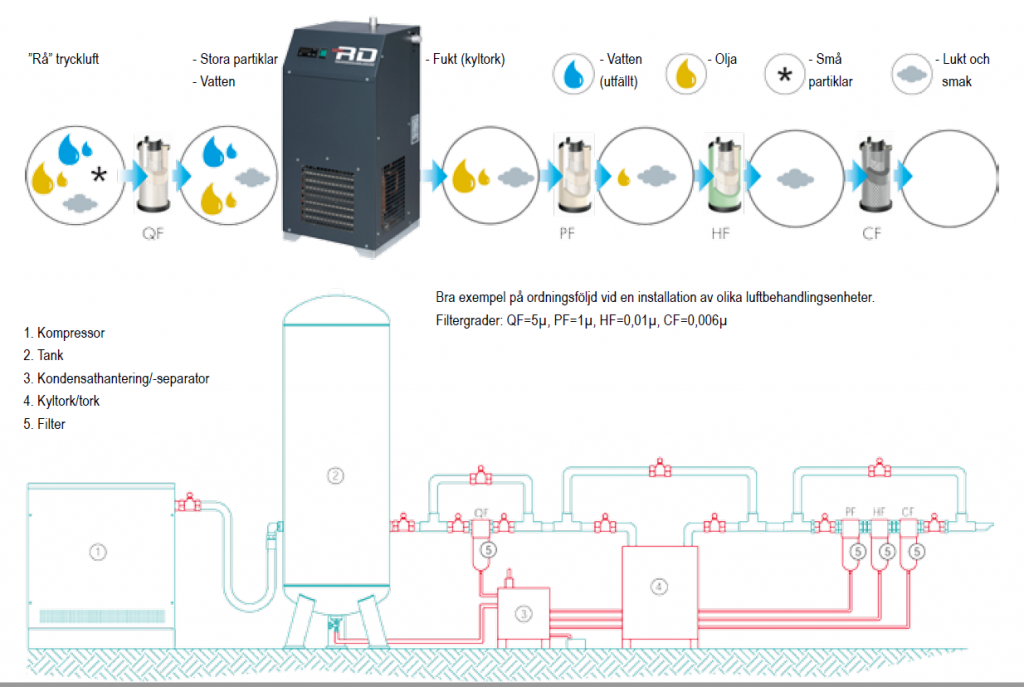
In larger compressor plants, it is also common to have different after-treatment of the compressed air to meet the different requirements.
Examples of how to treat compressed air for water, oil, odour and taste:
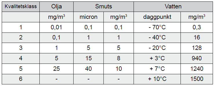
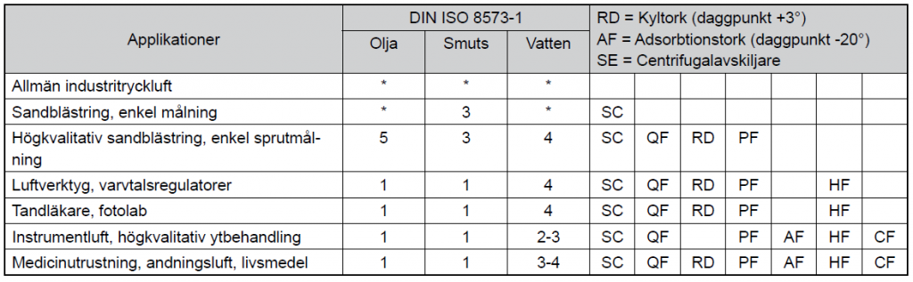
Examples of ISO Classes for compressed air, and which classes can normally be used for different applications
COMPRESSOR
Compressors can be of different sizes and have different ways of compressing air. The most common is to drive the compressor with an electric motor and unless we mention otherwise here, the values and explanations refer to electric motor driven compressors.
Some common types are:
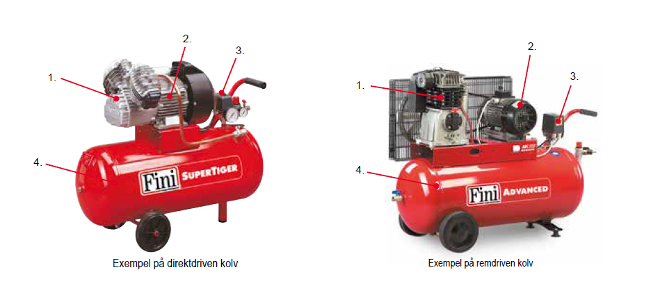
- Piston (Fini 0.6 - 15 kW)
- Screw (Fini 2.2 - 75 kW)
- lamella
- Turbine
- Scroll
The size we can normally talk about is the compressor's ability to deliver compressed air, i.e. the ability of the compressor block and the electric motor. The flow we are talking about is normally stated in Sweden as free air output in litres/minute
or other volume/time unit, see more info under air volume below.
To provide the compressor with a buffer of compressed air that can vary with the often varying demand, the you can also have an air reservoir directly connected to the block, but the size of the air reservoir has nothing to do with the "size of the compressor", which should be determined mainly by the strength of the electric motor.
An electric compressor functionally consists of:
- Compressor block
- Electric motor
- Pressure switch
- Air Receivers
The pressure switch is what controls the operation and in this there is a maximum pressure set, where the compressor stops, and a delta pressure, i.e. the pressure range where the compressor should work. The maximum pressure and delta pressure are also adapted for each given compressor, its fuse, safety valves and the like AND SHALL NOT BE CANCELLED IF by other than authorised personnel.
Of course, the different types also have more functions and their own special solutions to facilitate and streamline operations.
Piston compressors and screw compressors, in more detail:
RECIPROCATING COMPRESSOR
The electric motor can be direct or belt driven, oil-lubricated or oil-free, and single or two-stage. The piston pushes the air past the valve plate in the cylinder head where the actual compression (and most of the heat) occurs.
Usually air-cooled, two-stage models can also have coolers between the stages, it is also the cooling between the stages that increases the efficiency of these models.
ALL reciprocating compressors should be calculated to have a load rating* < 100%, normally the load rating ranges from about 50% on hobby models to about 80% on industrial models.
THE SCREW COMPRESSOR
The electric motor can operate directly or with a belt and as on-off or speed-controlled. Two screw-shaped profiles with a very precise fit rotate to compress air mixed with oil, the oil to cool, seal and lubricate and separate from the compressed air in the separator filter.
An electronic box normally monitors the whole process and the screw compressor, thanks to being cooled by the oil, has a load factor* = 100%
BRIEFLY ABOUT COOLING AND VENTILATION
All compressors create a lot of heat, but how much of the utilised power becomes heat can vary slightly with efficiency. However, the laws of physics dictate that at a certain compression there will also be a certain temperature increase. For example, at the valve plate of a piston compressor with a maximum pressure of 10 bar, the temperature at full operation is about 200ºC.
As a basic rule, the ventilation area needed to remove the heat from the compressor room should be at least equal to 2 x the area of the compressor fan (1 x the area into the room at the floor and 1 x the area out of the room at the ceiling).
*The load factor indicates how much of the total operating time the compressor can be fully loaded.
CHOICE OF COMPRESSOR
Choosing a compressor starts with deciding what you want to do with the compressed air, however, this is often already given, and if it is, there is often a spec. from some manufacturer on what pressure and what flow they require.
Use the suppliers' information about the machines you have, do your homework, but take the flow rates with a healthy pinch of salt, always expect to need some excess capacity in the end. There are various questions that can be good to answer BEFORE you even start looking at compressors:
- How much air is needed?
- What working pressure should I require?
- What compressed air quality requirements might there be?
- Where will I place the compressor?
- Is there enough power in the house?
Once you have identified your compressed air needs, there are also more things to consider before choosing the actual size and model of compressor
Choice of compressor
- Max. load on different models (hobby compressor for example approx. 50%)
- Connection cable (length and dimension).
- Ventilation (supply and exhaust air).
- Sound level, what can we accept
- Service accessibility?
Once all these questions are answered, you can choose and install a compressor and peripherals that can give you what you need. The only thing left to do to get started is to get the power from the compressor to each point of use in the right way, see the section on pipework below. To help you answer some of the questions above, you can also use the tables below.
PIPEWORK SYSTEMS
Your pipework is what conveys the power to your air tools, and since it's high flow, the well-known truth is that the chain is only as strong as its weakest link. An undersized or dilapidated pipework system, for example, could well bring down the efficiency of the air user to 50%.
Here are some simple tips for those who want to build their own pipework:
- Ring line, you should always start with a slightly "oversized" trunk that feeds from two directions, otherwise you risk getting pressure drops at the edges of the system, in addition, if you want to expand the system, it may be limited from the start.
- Flow, always keep flow in mind when planning and building, the right PRESSURE can always be achieved through a straw with a little time, but every bend, every curve and every sharp edge in the system will inhibit/slow down the flow and reduce the efficiency, in other words, think before and plan the most efficient system possible.
- Air quality, you should think about the air quality you want, and build in the filters, condensation columns and any dryers you may need from the start, otherwise a lot of extra work can arise when you notice that there is water in the air, for example.
- Accessibility, you should keep in mind that the workplace is usually not static, it changes continuously, so should the pipework. It is then good if all parts are easily accessible. This applies in particular to all air outlets and filters etc., otherwise it is easy for filter inserts to never be changed, and for long hoses to be used instead of pipes, with pressure drops and problems as a result.
- Accuracy, once you have planned a good pipework system, don't rush to install it and don't compromise on accuracy. A hole of Ø 1 millimetre can leak about 60 l/minute at 6 bar pressure, this means that if you have a compressor of 1 cubic metre/min and a pipe system with four small holes of Ø 1 millimetre, the losses after the compressor are already up to 20%.
ELECTRIC MOTORS
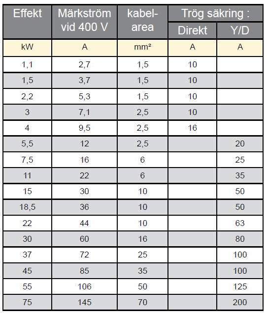
The values in the tables below are guide values and are only a recommendation. Always consult a qualified electrician for detailed information and installation.
Rated current is the current the electric motor draws from the grid at 100 % load and at the specified voltage.
The recommended main fuse for compressors is the conventional "slow-blow" type with a value of at least 1.5 x the rated current of the motor; automatic fuses should also be of the "slow-blow" type.
Starting current is the current consumed by an electric motor during start-up. The starting current is directly proportional to the rated current of the electric motor.
For direct start, the starting current of compressors is calculated to be about 7 times the rated current.
At Y-D start, the starting current can be calculated at about 2.5 times the rated current.
The insulation class shall describe the ability of the electric motor to withstand temperature rise in the windings.
The most common insulation classes are F and B.
B can withstand a winding temperature of +130°C
F can withstand a winding temperature of +155°C,
both are designed for +40°C ambient temperature.
Protection classes
The protection class of an electric motor or equipment is indicated by the letter IP followed by two digits.
Common protection classes for compressed air equipment include IP23, IP54, IP55 and IP65, some simple hobby models
also have IP20 and these must not be used outdoors.
The first digit indicates protection against contact and penetration, the second digit indicates protection against liquids.
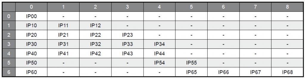
First digit: degree of protection against contact and ingress of solid objects.
0 No protection against penetrating objects.
1 Protection against touching dangerous parts with the back of the hand and objects with a diameter greater than 50 mm.
2 Protection against touching dangerous parts with a finger and solid objects with a diameter greater than 12 mm.
3 Protection against touching dangerous parts with tools and solid objects with a diameter greater than 2.5 mm.
4 Protection against touching dangerous parts with wire and solid objects with a diameter greater than 1 mm.
5 Protection against touching dangerous parts with wire. Also called dust-proof.
6 Protection against touching dangerous parts with wire. Also called dustproof.
Second digit: degree of protection against liquid ingress.
0 No protection.
1 Protection against vertically falling water droplets.
2 Protection against vertically falling water droplets and when the enclosure is tilted up to 15°.
3 Protection against splashing water.
4 Protection against overexposure.
5 Protection against water jets.
6 Protection against strong jets of water.
7 Protection against impact during short-term immersion in water.
8 Protection against the effects of prolonged immersion in water.
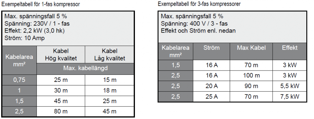
CABLE DIMENSIONING
What should apply to each individual site must be assessed by a qualified electrician. The tables below are just a guide to what you can expect, or roughly what you have to adhere to
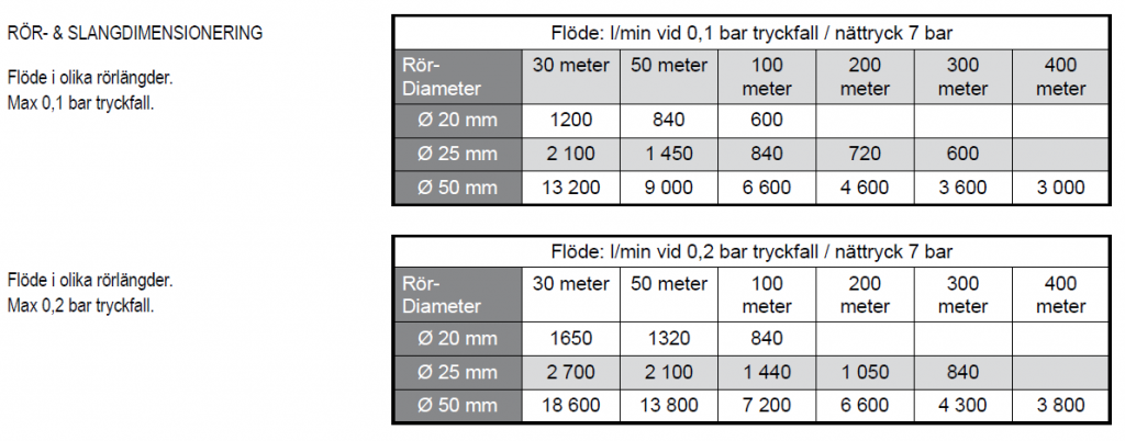
Flow in different pipe lengths with 0.1 and 0.2 bar pressure drop
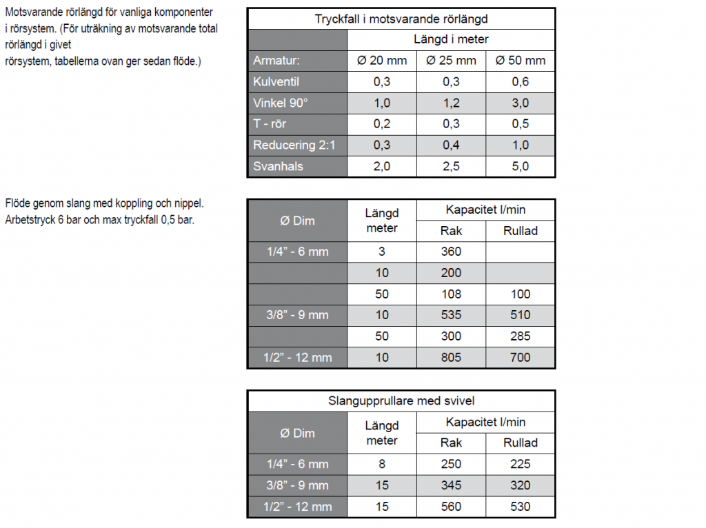
The corresponding pipe lengths of the fittings, and the flows through the hose with coupling and nipple at 6bar working pressure and 0.5bar pressure drop
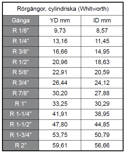
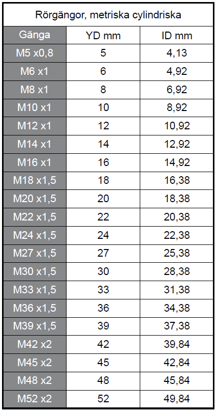
Below, Inner and outer diameters of pipe threads
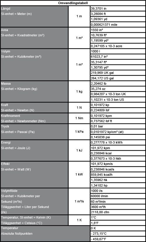
Below, Conversion table Units, for example pressure and flow